Clearance sale
Tekbox TBTC1 – Open TEM Cell for EMC Pre-Compliance Testing
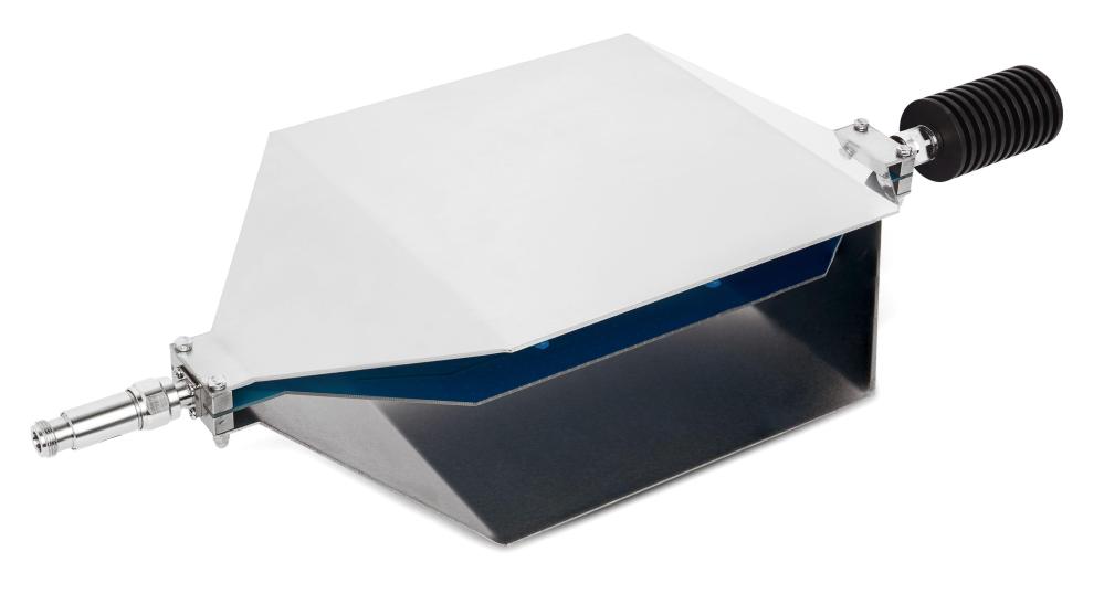
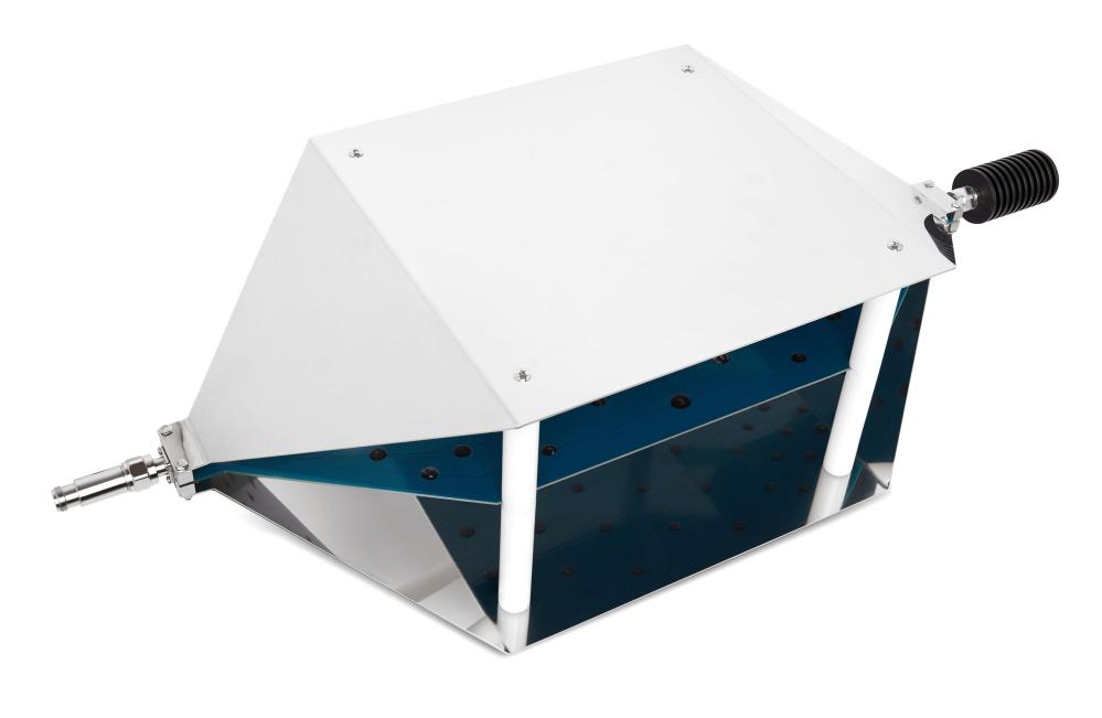
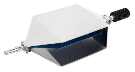
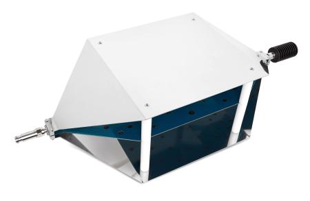
The Tekbox TBTC1 is an open TEM cell designed for radiated emission measurements and electromagnetic immunity testing of electronic devices. It is used for EMC pre-compliance testing to evaluate the EMC performance of products before submitting them to an accredited test laboratory.
Traditional radiated emission measurements are typically performed using antennas in an anechoic chamber. A TEM cell provides a compact and cost-effective alternative for comparative measurements during product development.
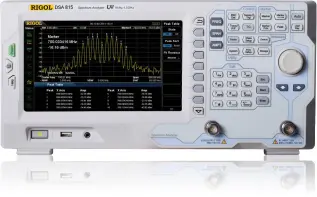
Combined with a spectrum analyser, the TBTC1 can be used to investigate how design modifications affect radiated emissions. Although these measurements do not replace full EMC compliance testing in a test laboratory, they help identify interference problems and evaluate improvements in an in-house development environment.
Design and Operation
A TEM cell consists of a centre conductor, known as the septum, and grounded conductive walls. This arrangement forms a 50 Ω transmission line, with the device under test (DUT) positioned between the septum and the bottom wall.
The TBTC1 features an open design for convenient placement and connection of the DUT. As the cell has no side walls, ambient RF interference may affect measurements. Background noise can be identified by measuring the signal level before powering on the DUT.
Tekbox TEM cells incorporate a design that suppresses higher-order wave modes and resonances, helping to extend the usable frequency range.
Dimensions and Test Area:
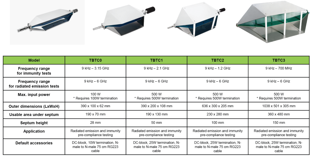
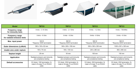
- Length: 390 mm
- Width: 200 mm
- Height: 108 mm
- Septum height: 50 mm
- Rectangular area beneath the septum: 190 × 130 × 50 mm
Specifications
- Connectors: N-female
- Nominal impedance: 50 Ω
- Wave impedance: 377 Ω
- Maximum RF input power: 25 W (limited by the supplied 50 Ω termination)
- Input return loss (S11): better than 20 dB up to 1.2 GHz, better than 17 dB up to 2.1 GHz and better than 14 dB up to 3 GHz
- Transmission loss: less than 1 dB up to 1.4 GHz, less than 3 dB up to 2.1 GHz and less than 6 dB up to 3 GHz
Included Accessories:
- 50 Ω / 25 W RF termination
- DC block to protect the spectrum analyser or RF receiver input
- N-male to N-male coaxial cable
DC Block 50V-6GHz-N
- Connectors: N-male/N-female
- Nominal impedance: 50 Ω
- Maximum continuous RF power: 2 W
- Maximum continuous RF voltage: 50 V RMS
- Frequency range: 500 kHz–6 GHz
- VSWR: ≤ 1.2
RF Termination 50Ω-3GHz-25W-N
- Connector: N-male
- Nominal impedance: 50 Ω
- Maximum continuous RF power: 25 W
- Frequency range: DC–3 GHz
- VSWR: ≤ 1.2
- Third-order intermodulation: ≤ 120 dBc